Post-tension (PT) cables reinforce concrete structures, providing flexibility and strength that allow for taller, safer, and more efficient construction. When grouped into clusters of three to five cables, they are referred to as banded PT cables. These configurations significantly improve slab strength and are commonly used in elevator shafts, parking garages, transfer slabs, and beam-supported floors.
How to Locate and Safely Cut Near Banded Post-Tension Cables?
Striking even one PT cable during cutting or coring can compromise structural integrity, create safety hazards, cause downtime, and cost up to $30,000 in replacement. The risk multiplies in banded PT slabs, where cutting through multiple cables could lead to catastrophic failure.
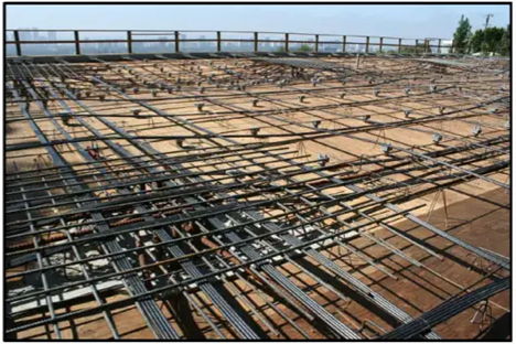
Layout of banded and uniform PT cables in a two-away configuration, with rebar and other reinforcements for a concrete slab, pre-pour.
Before cutting, coring, or drilling, it is essential to locate all PT cables, conduit, and reinforcements, then mark their positions clearly on the slab to prevent accidental strikes. For projects requiring full interior slab visualization, advanced reality capture tools can generate detailed 2D and 3D as-builts, provided the appropriate technology and expertise are available.
What’s the Difference Between Uniform and Banded PT Cable Layouts?
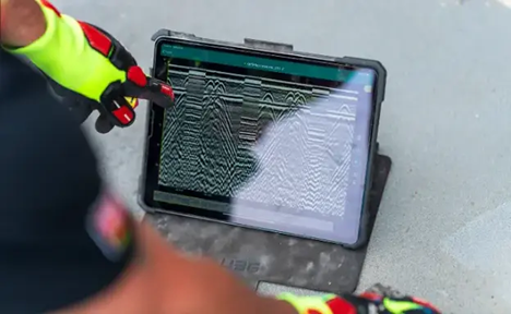
Close-up of a tablet screen showing the dense signals from a GPR array that show up on the screen as hyperbolas.
PT cables, also called tendons, can be installed in a uniform layout, where they are evenly spaced every 2 to 3 feet throughout a slab for general reinforcement. When additional structural support is required – such as around columns, elevator shafts, or large-span transfer slabs – PT cables are bundled together into banded groups for increased load capacity.
Step 1: Gather Necessary Equipment
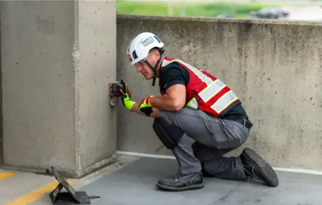
Accurate PT cable detection requires a combination of advanced scanning technologies and marking tools:
1. Ground Penetrating Radar (GPR)
- Uses radio waves to detect PT cables and other reinforcements inside concrete.
- Displays results as hyperbolas, which must be interpreted by a trained professional.
- GPRS SIM-certified Project Managers achieve 99.8% accuracy in cable detection.
2. Electromagnetic (EM) Locating
- Detects metallic objects and electrical conduits embedded within concrete.
- Used alongside GPR for secondary verification to ensure all reinforcements are accurately marked.
3. Concrete X-Ray (if applicable)
- Provides precise imaging, but is time-intensive and requires radiation safety precautions.
- Rarely used due to long processing times and additional hazards.
4. Chalk or Paint Marking Tools
- Options include spray paint, paint markers, chalk, or temporary adhesive markers for non-permanent markings.
Step 2: Perform Site Evaluation & Gather As-Builts
Before scanning, review structural drawings (if available) for:
- PT cable layout diagrams
- Planned core locations near columns
- Any prior markings from past investigations
Existing documentation is often outdated or incomplete, so it is crucial to verify as-built records through GPR and EM locating scans before cutting or coring.
Step 3: Scan for PT Cables Using GPR
- Calibrate the GPR based on slab thickness and material composition, considering dielectric values affected by moisture and slab type.
- Sweep the surface in a grid pattern to ensure full coverage.
- Identify banded PT cable zones, which appear as concentrated clusters of hyperbolas in scans.
- Verify findings with EM locating to confirm metallic reinforcements.
- Mark detected cables clearly with chalk or paint for reference during cutting or coring.
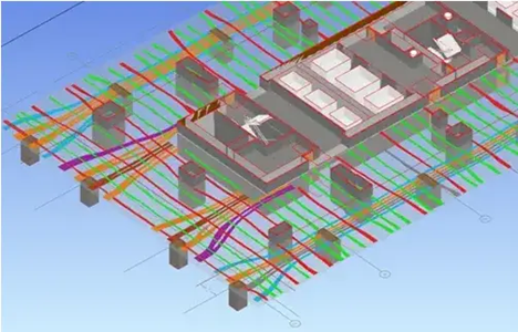
A screenshot of a brightly colored 3D BIM model depicting the interior of a post tension concrete slab.
Step 4: Determine Safe Coring and Cutting Zones
- Measure the spacing between cables to identify safe areas for coring.
- Mark a buffer zone—typically at least three inches away from any cables.
- Align cutting or coring locations with confirmed clear zones.
- Consult structural engineers if necessary before proceeding.
Step 5: Safely Cut Through Concrete
After final scan verification, cutting and coring can begin. Best practices include:
- Using water suppression to minimize respirable crystalline silica (RCS) exposure.
- Preventing pinch points and kickback to reduce injury risk.
- Following industry safety guidelines, including protocols from Concrete Sawing & Drilling Safety Week (CSDSW), sponsored annually by GPRS.
Concrete Cutting and Coring: Safety & Execution
Now, it’s time to cut, core or drill. It’s important to adhere to best practices, including those that mitigate exposure to respirable crystalline silica (RCS). Prolonged inhalation of RCS can lead to silicosis, an incurable lung disease. Workers can learn more about silica exposure, pinch points, and kickback hazards during Concrete Sawing & Drilling Safety Week (CSDSW), sponsored annually by GPRS.
GPRS does not offer concrete cutting or coring services but prioritizes jobsite safety. The following steps outline best practices for executing these tasks.
Step 6: Cutting and Coring Procedures
- Wear OSHA-recommended personal protective equipment (PPE).
- Use wet-cutting systems to suppress silica dust.
- Employ low-vibration coring rigs to minimize stress on adjacent concrete.
- Drill a pilot hole to check for cable interference.
- Monitor core depth to avoid disturbing embedded cables.
- Conduct full cutting or coring within designated safe zones.
Step 7: Post-Cut Inspection and Documentation
- Inspect the core site for signs of cable proximity or tension changes.
- Assess slab integrity to ensure no structural compromise.
- Update site records with accurate cable location data for future reference.
Using a project or facility management tool like SiteMap® (patent pending) from GPRS simplifies documentation, versioning, and data aggregation for concrete-related projects.
Enhanced Visualization and Modeling
GPRS utilizes reality capture technology to generate precise 2D maps and 3D BIM models of post-tensioned concrete slabs. Advanced scanning methods, including laser scanning and photogrammetry, enable high-accuracy digital representations of internal slab structures. These models can provide streamlined and safer project execution, particularly in identifying and marking banded PT cables.
Final Considerations
- Consult structural engineers before cutting post-tensioned slabs unless cable locations are fully verified
- Always scan the worksite, regardless of existing documentation
- Use multiple detection methods for improved accuracy
- Follow OSHA-prescribed safety regulations, including wet cutting and proper PPE
Proper concrete scanning, marking, and cutting practices safeguard both structures and workers. Hiring a professional concrete imaging company like GPRS reduces risks, ensuring precise visualization of embedded elements.
Why GPRS?
GPRS is the only concrete imaging company that offers the Green Box Guarantee. When our Project Managers mark a green box labeled CLEAR, we guarantee the area is free of obstructions – and if we’re wrong, we’ll pay the cost for material repairs.
GPRS Supports Safe Infrastructure Improvements Through:
- Ground Penetrating Radar (GPR) & Electromagnetic (EM) Locating for high-accuracy PT cable detection.
- 3D Reality Capture & Modeling for site visualization and long-term asset management.
- Industry-leading SIM certification standards, ensuring 99.8% accuracy in subsurface mapping.
Before breaking ground, ensure your team’s safety and project success by mapping all PT cables, conduit, and reinforcements. GPRS’ mission is to Intelligently Visualize The Built World® for customers nationwide. What can we help you visualize?